|
Below are some great tips and tricks that I have compiled while building the 601HDS. If
you have any ideas that would help a fellow builder, please e-mail me at don@pcperfect.com and I will be glad to add it.

General
 | I'm currently working on the project after work and on weekends. On particularly
hard days at work it is often impossible for me to concentrate. I'm caught in desperately
wanting to work on the project, but not wanting to screw things up. I've learned that it
is best to put the project off until my mind is 100% into doing it right.
One of the ways I catch myself doing the wrong thing is whenever I start mentally saying,
"it probably won't matter- what's a little ?" or something similiar. Then I know
it's time to quit. In the end, that kind of workmanship is not the plane that I want to
trust my life to. |
| I work at my regular job full time, but do "something" every
day on the zodiac. When I have difficulty understanding a part of the construction, I
allow myself to sleep on it, and somehow it becomes clear the next day. Don't forget to
get moral support as well as technical from other builders in the area. Go for it!
|
| Where do I get Rivets if I don't want to purchase from ZAC
(article taken for Matronics List)
If your intention is to follow the plans... and I > think it is
reasonable to do so, you need the
countersunk (flat) rivet head. The part nos are: 01604-00412 for
the A4 rivet, 01606-00514 for the A5 rivet.
Avdel Textron takes orders on the phone with credit > cards. The
phone number is 800-268-9947. Their web site address is www.avdeltextron.ca.
Don't be surprised if you don't find these part nos.
in their catalog... these are the UK rivets. The US rivets have
the following part nos. 1682-0412 and 1682-0514. C. Heinz
recommends the UK rivets |
Measuring
| Use a block(s) of wood or similar material clamped to your table to help
mark the centerlines on your ribs and various other items. This is especially helpful when
you have to mark centerlines on multiple ribs, etc. Just get the proper distance from
table to top of the top of your clamped wood. This needs to be the correct distance to
your rib centerline and use the wood to mark your line. |
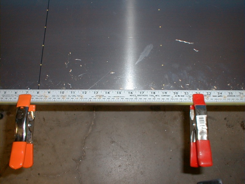
| Take a ruler (metal based seems to work best) and pre-drill your rivet
pitch actually into the ruler. You can then clamp the ruler to your work and use the ruler
as a drill guide and end up with really nice and straight rivet lines. Especially in areas
where you need to do 10 or more rivets and you have a straight line for reference. To see
a picture of me using the ruler template on the wings just click, Ruler Template Picture. (BTW, you may notice in the
picture that some of rib rivet lines are not straight. These unfortunately were done by
Zenith. If you take your time and make a good template, the end results are fantastically
straight rivet lines.) |
Rudder
Elevator
| Installation of the Elevator Trim Piano Hinge - Rivet the elevator trim's piano
hinge to the elevator before riveting the elevator's top skin. Once the top skin has been
riveted there isn't enough clearance for the A4 rivets. Two local builders (myself
included) waited until after riveting the top skin which required us to prop up the hinge
just enough to provide clearance for the rivet and try to "pull the rivet" at
the same time. |
Stabilizer
| Make L angles out of wood to properly align the ribs to the spars. If you use 2
pieces of 1x3x10 wood butted together to make a 90 degree angle this will not only help
keep all angles perpendicular as necessary, but also stiffen the structure while building.
Make sure you have enough clamps on hand. I needed approx. 10. There is a picture of this
in the photo album stabilizer section (photo album). |
| Use my pre-made drilling template for the rear spar attachment. A great time
saver. In Adobe Acrobat Format - Rear Spar Attachment
Drilling Guide. |
| Use spacers for the two outer ribs that are beyond the doublers. This will make
installing the stabilizer skin easier and require less trimming. This is because the spars
bow inwards at the edges (both rear and front) since the outer ribs on each side are
effectively shorter than the inner ribs (inner ribs are installed over the doubler which
adds approx. 2mm, outer ribs are attached directly to the spars). Since the skin is cut
perfectly, it makes it hard to line up the edge of the skin to back of the bowing spar. |
| Strap the skin properly to ensure you don't damage the delicate stabilizer
skeleton. When strapping the skin to drill the top side I didn't understand why ZAC called
for running the straps underneath your work bench. If you don't you easily bend the rear
spar when tightening the straps. Also, be careful not to over tighten the straps. Very
tempting and will tend to warp the stabilizer skeleton and create a ghost image of the end
ribs on the stabilizer skin. |
Outer Wing Sections
Found that putting some lipstick on the drain hole is a
great way to mark the hole position. Just keep in mind that as the top skin
compresses the cork, the hole may move slightly. Came up with a neat idea for
the filler hole. Took a 2 1/2" hole saw, laid it on a piece of 12" x
12" construction paper. Marked the outline of the 2 1/2" hole. Cut
out with an exacta knife. Laid paper on the fuel tank (install in wing without
the nose skin on). Punch holes in paper that matched up with rivet holes.
Clecoed paper. Made sure hole was centered around filler neck. Un-clecoed the
paper and moved it to the nose skin. Clecoed used the same matching holes on
the nose skin. Drilled out filler neck hole. Only done this on the first wing,
but it came out great. Hope to have some pictures on the second wing. Digital
camera is in the shop for repair.
| Rear O/B Splice Plate - Use my pre-made drilling template. In ADF format - Rear O/B Splice Plate Drilling Guide |
| Tech Support E-Mail Q&A: In reference to the Leading Edge
Fuel Tanks - Replacement Rib 7A touches (interferes) with the buck rivets on the main
spar. What should be done? (Cover them, drill them out, drill a hole in the NR7A,
etc.)
Response from ZAC: You are right, the rib should not interfere with the
solid rivets, the following are two approaches to attaching the Nose Rib 7A at station
410mm:
1) The solid rivet underneath the rib flange 7A can be drilled out and replaced
with a solid rivet through the rib flange or with an AN3 bolt through the rib flange
and the Spar extrusion.
2) Leave the solid rivet in the Spar and make a cutout in the rib flange to clear the head
of the solid rivet. Reinforce the side of NR 7A with a length of L angle (same
width as the Rib and Spar) riveted into the rib web and into the spar with seven A5.
The L angle goes on the outboard side of the Rib with .040 angle on the inboard side of
the Rib. |
| Tech Support E-mail Q&A: In the Speed Wing Plans for the
601HDS it shows the Rear O/B Splice Plate
with the 20 degree cut on the bottom and the 33 degree cut on the top. In the draft PDF
Speed Wing Instructions it says and shows the reverse (20 on top, 33 on bottom). Which is
correct?
Response from ZAC: Placing the 20 degrees on the top will mean
better clearance on the bottom for
the aileron push rod. However both will work, it would just appear better to do less
filling! |
| Tech Support E-mail Q&A: Are the fuel caps vented? Response
from ZAC: The cap is vented underneath the side flanges, the two little
hole in the middle of the cap are interconnected with the side
flanges: blow through the middle holes to check they are free! |
| Tech Support E-mail Q&A: Should I seal all of the threaded
fixtures with a TFE type paste (with
Teflon) compound to prevent leaking? If so can you recommend a brand? Or is a
standard plumbing pipe thread compound OK? Response from ZAC:
Use extreme caution when using Teflon tape: keep the edge of the tape back
from the end of the fitting to show at least 2 threads on the fitting - do not start
the tape flush with the end of the fitting: the NPT thread will allow the tape to come
loose and restrict the fuel flow. |
| Tech Support E-mail Q&A: The gascolator has four threaded
openings. I can only figure out what 3 are
for. Can you give me directions on how the fuel flows into the gascolator. My guess
is that two of the openings are for fuel coming into the gascolator from the wing tanks.
One opening is for the for the 1/8" drain and the fourth is for the outgoing
fuel line to the header tank. Is this correct? Response from ZAC:
The gascolator for the wing locker tanks connects the left and the right tanks at
the gascolator with one outlet to the header tank. The fourth hole is the drain at the
bottom. |
| Tech Support E-mail Q&A: You have provided an area to
mount a fuel gauge sender unit on the side of the L/E tank. Can you recommend a
specific unit that you know will work with the tanks? Response from ZAC:
The tapped holes have an SAE 3 bolt patter common to most automotive float type of fuel
sender units. An alternative fuel sender is an inductor bendable probe as available
by Skysport at 1-800-AIR-STUFF |
| Wing Baggage Lockers: Be careful when trimming the hinges.
This must be done after reversing the hinge. When the hinge is reversed it moves over one
"slot" which offsets the hinge if trimmed before reversing. |
| Tech Support E-mail Q&A: What are the grounding cable
attachment points for the LE HDS Fuel Tanks?
Response from ZAC: The tanks is supplied with
welded tab, this is specifically installed as a mounting plate for the grounding cable. |
| Tech Support E-mail Q&A: What is the
best way to secure the grounding cable (rivet, screw, AN bolt, etc.)?
Response from ZAC: This will depend somewhat on what type of
electrical fitting is installed at the end of the grounding wire: if the right size
hole cannot be found then a bolt would be preferred. |
| Tech Support E-mail Q&A: What gauge
wire should be used for the grounding cable?
Response from ZAC: Grounding wire was not supplied in the
kit. This does not have to be a very large gauge wire, #10 should be more than
adequate!
|
Center Wing Section
| One builder's results of industrial plating his struts,
etc. ...
<< I located a plating company that I think is a first class
operation, operated by some really nice folks, and charges what I think is very
reasonable. I tell you what, I really got an education about plating. Some of you
already have hard-chromed your struts, etc, but for the rest of you I'll pass along some
information that might come in handy. True Industrial Hard Chrome is not like
"bumper chrome". If you turn in a part that is polished like a mirror,
then you will get a part back that looks like a mirror. What ever your struts look
like when you turn them in.. they will not look better than that when you get them back,
but will be plated with this stuff that is harder than you would ever believe, no rusting
problems to worry about, and extends the strut life. I was told by someone else that the
hard-chromed areas will not wear your strut bearings out as fast as unplated steel on
aluminum contact. I turned my stuts in after I had polished them up with emery
cloth. I also decided to plate my control stick assembly and the two steps that
stick out behind the wings. After a discussion with Rich at Chrome Wright Inc., he
convinced me to use a combination of hard chrome and nickel plating. He showed me
that contrary to nickel plating that virtually plates every nook an cranny, inside
threaded holes and so forth, that hard chrome won't plate very good into recessed corners
and holes (like where the mounting plates are welded on the strut tubes). I wound up
polishing the control stick with emery cloth, and getting it plated in nickel. Looks
Dynamite! He then glass beaded the step tubes (which produces a really nice looking micro
texture), and plated them in nickel, and that looks great too. The main gear struts are
plated with hard chrome and because of what was pointed out to me before we even began
plating, I will spray the lower mounting plate with a blending metallic paint. The
nose gear strut was hard chromed in the bearing areas, glass beaded and nickel plated in
the areas of the cross members, bolts, and the lower strut tube and mounting plate.
Because he used nickel on the lower portion of the nose gear strut, it looks
terrific and the plate won't have to be painted. If you don't find someone in your
area to do this for you, consider these folks. I asked him for some prices and
information to pass along to you guys on the net and I received the following.
**Prepare the parts to look like you expect them to look when they are done. The
industrial hard chrome will not build up and smooth things out. Be sure to remove
ALL the "mill scale" (that's the black coating that's on the stick and step
tubing). The pricing is as follows: The two main gear struts are
$90. a pair. Nose gear strut is $55. Steps are $45. for the pair, and the
stick is also $45. The person to contact is "Rich" at Chrome Wright, Inc.
97 East Oldham Parkway, Lee's Summit, Mo. 64081 Phone number is (816)
525-5417.
Remember, the good experience I had with these folks is like getting a great meal at a
restaurant and then passing the recommendation along.... Don't assume that by just sending
something in, that you will be just as pleased. You need to talk to him thoroughly, and
make your own decision and arrangements. All I can say is that I like what I got,
and think Rich is a really first class guy to do business with. Hope this
information will come in handy and be of a benefit to some of you. "Soft
Landing".. Fred >>
|
| Adding Bearing Material for Gear
Slides, Lower Bearing, and Upper Gear Plate.
A lot builders, myself included, have put UHM(PWE/W), Delrin, or
Nylon on the gear slides, lower bearing, and upper gear plates. Some
builders have reported no appreciable wear after over 150 hours of flight.
While those using only grease have found considerable wear after the 150+
hours. I went ahead with UHM material because it doesn't expand and contract
as much as Nylon. Didn't go with Delrin just because I wasn't familiar
enough to know the pros and cons. If you decide you'd like to go with UHM,
it can be purchased from Cadillac Plastics @ (800) 274-1000 or (480)
275-6295. Would suggest ordering 12"x12" sheets of 1/4" and
1/2" and use as needed.
|
Fuselage
Instrumentation
| Calculating TAS using a known ground distance by Michael Cooper: |
You need two legs, reciprocal to each other.
Plot the distance and course between the two VORs you want to use, then fly that course
and it's reciprocal. Do not correct for wind; head/tail or x-winds will cancel out on the
inbound and outbound legs. Time the legs, then average them. You now have a known distance
on the ground with the time to fly it.
To do this, fly the course between the two VORs but ABEAM the VORs, i.e. a few miles to
the left or right parallel to the antennas and set your OBS for the radial 90 degrees from
your course. For example, say the course between the VORs is 180 degrees. Fly 180 a couple
of miles west of the VOR, with 270 selected in the OBS. When your needle centers on the
OBS, start
the time. Now set up for the next VOR using the same radial. Maintain 180, and when the
needle centers, stop the time.
This way, you avoid the ambiguity directly above the antenna.
Also, when you do the TAS thing with the VORs you need to fly both courses at the same
altitude for accurate results, so it's
necessary to coordinate with the FAA as you'll be busting the hemispheric cruising
altitudes.
From Don Honabach: Buy a GPS and be poorer, but HAPPY!
Firewall Engine
Maximizing Cruise Speed
The following two articles were taken from the Zenith Internet Newsgroup.
| How to get the most performance from your airplane: |
1. To get a good comparison with the manufacturer's
published figures it's necessary to know at what power setting THEY were published at.
Most production aircraft publish max. continuous cruise numbers for 75% power, as that is
the engine's max cont. cruise limit. I assume it's the same for the 601/Rotax
combination??
2. In order to get this setting on a new prop/engine
installation I assume one has the manufacturer's charts etc. available to convert rpm vs.
altitude & temp. into % power. The maximum cruise speed occurs at the altitude where
75% power is achieved with the throttle wide open. This usually happens around 7 to 8,000
feet (+/-) for a normally aspirated engine (i.e. no turbocharger).
3. The accuracy of the tachometer readings are
important here. The tach. in the factory demo I flew was not easy to read in detail (i.e.
only one hand on the scale), so flying at full throttle at the altitude which will limit
power to 75% seems like a good way to also 'calibrate' the tach readings.
4. All of the above is also affected by the
propeller
pitch setting, as mentioned by Bernie. A judicious choice of prop angle is required to
balance cruise speed with take-off & climb performance. If you're flying from mostly
'real' airports, then why not sacrifice a few more feet of take-off roll to get a higher
cruise speed. By comparison, the takeoff roll for a Cherokee 140 at gross wt. at sea level
is 700 ft., increasing to 1,000 feet at 4,000 ASL (i.e. Calgary).
5. Once you've got a good idea that your engine
output is close to 75%, then the next step is to do some runs along a known track (or use
a GPS?) and calculate the TAS. Especially with a newly installed system I wouldn't trust
the IAS much until it's verified (see George Pinneao's experience finding a good location
for the static ports, etc.)
So I guess the GPS is really the best method to establish a true ground speed. To work
from there to a TAS, it seems to me you'd have to run at least a triangular course (or
maybe four legs n/s & e/w to simplify the math?). I'd have to sit down and work this
out a bit as I haven't done it yet and my math needs refreshing. Anyone out there have a
good formula for the least number of legs needed to derive the TAS from a known Ground
speed and track only?
If you can fly on a day when you KNOW that the wind is essentially calm at altitude, (btw,
the wind at the ground is NOT a good indicator of this), or get an ACCURATE read out from
another aircraft with an airspeed indicator that is PROVEN to be accurate, then it makes
the job easier.
6. All this to say that you want to REALLY know if
your aircraft is REALLY that much slower than the published figures.
7. If it is then some of the things to 'clean
up'(with only 80 hp. every little bit counts!!) - rigging: is it put together properly :-)
- wings both at the same angle? (notice any consistent trim tendencies?) - weight and
balance? properly in the envelope? (closer to the rear of the envelope is better for
cruise speed, but probably not significant in such a small aircraft...?) - are the
controls carefully adjusted to the proper settings - both ailerons properly 'faired' with
the stick centered, etc. (see previous comments, from George Pinnaeo? regarding aileron
settings) - Wheel pants? (spats?) ... Bernie, I think, has a good handle on how much
difference they actually make to the speed. - Radiator and oil cooler placement. I'm sure
they can have significant impact.- canopy sealed well? I know ventilation is a
consideration under that big dome, but ANY leakage will drag down the speed. - likewise
the engine cowling...care needed here to have sufficient airflow for cooling, but not more
than necessary. - all over the aircraft, check where air leakages might occur.
(control/fuselage joints, etc.) (that's the beauty of the flexi-hinge aileron; absolutely
NO air leakage) - did you install the fairing at the back of the fuselage where it meets
with the bottom of the vertical stabilizer? - install some kind of grommets/fairings where
control cables exit the fuselage (be careful about anything that might cause a jam!!)
8. I once heard Jim Bede at Oshkosh address the issue
of drag and I was surprised how much emphasis he put on small air leakages. (say what you
want about the success of his aircraft from a manufacturing point of view - his designs
are always very efficient in terms of speed vs. thrust!)- antennae installations can also
add a couple of knots drag! Again, with a small engine, small things really can add up. -
did you remember to replace all those clecos with rivets - they really add a lot of drag -
JOKING, JOKING....
| Your aileron's position can make a difference in your cruise
speed. |
An
interesting observation is that a friend flew with me and observed that my ailerons
"were up" meaning above the nominal trim-line, as he saw it. So, willing to
learn from reversable adjustments, I extended both the aileron push-rods somewhat to bring
both ailerons down to what he believed to be the appropriate trim-line. I then flew the
plane and felt no difference in smooth control, etc.
However, this adjustment resulted in a loss of about 3-5 mph in cruise!! So I reversed the
adjustment, bringing the ailerons back to their original "up" position; this
restored the speed.
Moral: slightly "up" ailerons is faster than "down" ailerons.
The following was a response to the above
message:
It is well known that reflexing ailerons and
flaps does increase cruise and maximum airspeeds, however, you are also increasing your
stall speed by fixing these control surfaces up a few degrees above neutral. You will find
that your stall speeds will be similarly reduced (to a point) by fixing them down relative
to neutral. This phenomenon is most useful if you can adjust your flap/aileron settings
"on the fly" (sorry) for cruise and landing/takeoff operations. I guess I would
say if you want higher cruise at the expense of higher stall speeds that is great. But be
advised that if you have your control surfaces positions fixed "up" relative to
neutral, you are most likely giving up some of your low end performance!
Brakes
|
Letter to Matco and Matco's Response
|
I received 3 Matco wheels and 2 MC-5 Master
Cylinders with my Zodiac 601HDS Kit from Zenith Aircraft Co.
Can you tell me what wheel(s) of yours they
use? I've looked at your web page and can't find an exact match.
I'm also trying to determine what would be the best material to use for
brake lines. Do you have any suggestions?
What is the min. recommended pressure rating for the brake line?
Are there any definite hoses / brake lines that shouldn't be use?
Do you have any instructions (for dummies) on how to fill up the break
system properly or a book to reference for the basics. I have no previous
experience and this is a bit overwhelming without any background knowledge.
MATCO Response:
Dear Mr. Honabach:
Because the wheels we manufacture for Zenith are custom to their
application, we do not have them on our web site at this time.
We recommend that you use a rigid nylon tubing for your brake lines.
This helps to prevent the expansion you get with softer poly tubing while
still having the advantages of a one inch bending radius a bursting strength
of 1700 PSI and clear tube for bleeding.
We recommend a minimum working pressure for your tubing of 450 PSI.
This is the absolute minimum recommended for the Zodiac 601HDS.
I would recommend against using the polyflow tubing as I believe it has an
operating range of 175 PSI and tends to expand under pressure. Many
customers have used this tubing over the years with great success however.
If you think you want to go this route, you should conduct a pressure test
to determine how much pressure you are exerting. Be aware that the
MC-5 master cylinder with a 2 1/2 to 1 mechanical advantage and a pilot
exerting only 150 pounds of force will generate 815 PSI.
This system bleeds very easily from the bottom up with a simple oil can.
If you would like specific information on bleeding methods, please take a
moment to send me your fax number and I can fax this information to you.
FiberGlass Primer
|
E-mails from Matronics News List about the
West system
|
Gougeon Brothers, Bay Cities MI, makes and
wholesales what I, and many thousands, call "WEST". It's a
system of epoxy resins, hardeners and fillers that let you do a bunch of
things from building cedar strip canoes to whole aircraft. You can get
all the technical insights you could possibly want from some of Martin
Holman's books but the Gougeon brothers sell their own technical hardcover
book on Boat Building. It makes an interesting read: from boats to 100'
windmill blades of Wood Epoxy Saturation Technique -WEST.
Pinneo's Rule # 48: friends don't let friends use polyester/glass. Use
EPOXY.
Pinneo's Rule # 3: Epoxies bond to each other and to polyester. This can be
very important in the air or on the water.
WEST epoxy/glass is simple, which is why it's used to repair beached
sailboats and 100' long windmill blades for the DOE. You don't have to
vacuum bag it, but that will give you more strength and less weight.
Hand layup is all I used to make 2 sets of wheel fairings, gearbox fairings,
aileron pushrod fairings, the canopy fairing, the spinner and about 4
different sequential cowl mods. (I've got to do another one of those
to get a sleeker, more attractive shape.)
Look up WEST Resins or Gougeon Brothers on the Net; they've a technical
manual online that's all you really need before you buy a pump-kit and make
a fairing. It's a little messy but you can handle that. It's
much less toxic than polyester, smells better, will really, REALLY bond to
things and is easy to sand and paint.
If you can visualize the fairing you want, you can make it in WEST.
You can use glass, carbon, Kevlar cloth in your composite. You can go
nuts and use honeycomb or balsacore. You can glass-in studs or
nutplates; you can get almost any shape conceivable.
You can learn to use it by using it; there are a lot of WEST-a-holics out
there!
GGP
--------------------
Hello. It seems like it would be a good
idea to install parts
like fiberglass wing tips, the fiberglass light fairing on the
rudder, etc., with some sort of anchor nuts so they could be
removed later for maintenance if necessary. What kind of anchor
nuts are folks using, and how are they attached? Are smaller
rivets commonly used? Are they epoxy'd in place in the wingtips?
Thanks for any help.
Bill
601HD Trike
--------------------
To create a captive threaded self-locking
fastener on a sheet metal part, use ACS #AN366F-832; this is an 8 x 32
elastic nut plate. $4.20 list each (ouch.)I drill out the two mounting holes
to accept A4 rivets.
To create a captive threaded self-locking fastener in a spinner skirt, wheel
fairing, cowl, etc., use an EZ-Point nut, ACS # 04-06370 @ $1.60 ea, and
just epoxy/glass it to the other fiberglass or epoxy part. You can use ACS
#0406330 which is a threaded stud @ $1.60 ea.
GGP
--------------------
West System can be found on the Web @ http://www.westsystem.com
|